Part of the Oxford Instruments Group
Expand

SampleProtect

Provides experimenters with an end-to-end method of protecting sensitive samples from accidental electrostatic discharge (ESD).

  • Can be used over a wide variety of temperatures with all of our products and new experimental measurement probes

  • High quality measurement grade cables

  • Low noise


Request Pricing Add to quote list

The SampleProtect concept is to provide experimenters with and end-to-end method of protecting sensitive samples from accidental electrostatic discharge (ESD).  The system comprises of a rack mount SampleProtect Switching Unit (SPSU) linked, via measurement grade cables and sample probes, with sample holders which include an additional socket for an equi-potential plug.  

The sample holders are demountable from the probe and each probe can accommodate multiple types of sample holder.  Also, sample holders are transferable between probes, or even to a HelioxVT or KelvinoxJT ULT insert.

  • System can be used over a wide variety of temperatures with all of the Oxford Instruments product range and new experimental measurement probes
  • High quality measurement grade cables
  • Low noise
  • Strong shielding
  • Low cross talk
  • BNC or Twinax option
  • 24 connectors and 12 twisted pairs
  • Fully earthed measurement grade cables for low level signals
  • Reliable build and trusted design
  • Material characterisation
  • Device characterisation
  • Optical characterisation
  • Opto-electrical characterisation
  • Electrical measurements
  • Quantum devices and other nanodevices

In addition to the screened measurement cable there is a low-pass multi-stage filter can be mounted at cryogenic temperatures down to below 100mK. This has the ability to filter 24 signal lines with filter options of 4 different cut-off frequencies.  The filter is constructed in an Au plated Cu chassis with RF gaskets to provide screening and thermal dumping for the filter PCB.  The filter components are carefully selected surface mount components which provide very good value stability over the temperature range from ambient to sub 100mK.

Cold Filter

During the process of mounting the sample into the sample holder, the ESD plug will be inserted.  This plug links all the electrical connections to the sample together ensuring that no damaging voltages can be generated across the sample due to ESD.  This plug remains in place during transport of the sample holder plus sample, meaning the sample could safely be taken from the sample preparation lab to the measurement lab, or even shipped to a lab in another continent safe from ESD damage.

When mounting the sample holder in the probe, the user keeps the ESD plug in place.  Then connect the probe to the desired measurement instrumentation via the SPSU.  Set the switches of the SPSU to ground all the signal lines to the desired ground, either protective ground or instrument ground.  Once the switches are set correctly, remove the ESD plug from the sample holder.  If appropriate for the sample the user might run some measurement checks to ensure the sample is connected and the signal train is working.  Then the probe can be loaded in the cryostat and cooled to the required temperature.

Once the sample plus probe is inserted in the cryostat and the measurements are in progress, the SPSU can be used as a break-out box to switch or monitor any of the signal lines during the experiment.

  • 3U high and designed for 19” rack mounting
  • 2 x 50 way rear mounted sub-D connectors
    • Connection to the signal lines of the measurement probe or cryostat
    • Feed-through link to connect any of the lines to additional instrumentation (an alternative to using the individual BNC and Twinax on front panel)
  • Unit switches can be used to switch any of the signal lines between signal, measurement ground or protective ground.
  • Each signal line has a BNC or Twinax port for connection directly to measurement electronics or diagnostics.
  • High-quality make-before-break switches
    • Low resistance Au contacts
    • Sealed against moisture ingress to avoid future contact corrosion
  • Internal signal routings designed to minimise cross-talk
  • Line resistance kept to a minimum

The measurement cable is a carefully specified cable constructed of 13 twisted pairs, 10 pairs of 26 (19/38) AWG tinned Cu and 3 pairs of 22 (19/34) AWG tinned Cu. Each pair is individually screened with a foil screen. Each screen has external insulation to isolate it from all the other screens.  Each screen also has a drain wire. 

In addition, the cable has an overall foil screen which has internal insulation plus an external screen braid.  The overall screen also has a drain wire.  This construction facilitates overall screening with the outer screen connected to protective ground but in addition any pair can be screened to a specific measurement ground for that channel.  The cross-talk increases with frequency as expected and is shown in specifications.

The PCB and LCC holders are ceramic Aluminium-Nitride (AlN) to optimise thermal conductivity.

Electrical contact plating is Ni free to minimise the remnant field effects in the sample domain.

The following sample holders are available:

  • 20-pin LCC with ESD connector
  • 16-pin DIP (dual in-line) connector with ESD connector
  • 16 contact pad bare pcb for general purpose with ESD connector
  • 44-pin LCC – NO ESD connector as there is not enough space

PCB sample holder interface – 44 non-magnetic spring loaded pins to connect to the sample holder PCB


Three standard probes compatible with the TeslatronPT:

  1. Fixed sample
  2. Mechanical rotator (Swedish rotator)
  3. Electrical rotator (Piezo drive

Each probe is available in Sample-in-Gas (SIG) or Sample-in-Vacuum (SIV) variants.  The probe chassis consists of 3 thin-wall stainless-steel tubes to provide a rigid, straight, low-thermal conductivity structure and create separate electrically isolated spaces to keep measurement looms shielded from diagnostic and drive wiring.


Specifications

ItemValue
Temperature Range0 to 40° C
Voltage rating50 VRMS
Recommended Frequency RangeDC – 100 kHz
Mutual Capacitance38 pF @1 kHz
Line Inductance< 0.30 µH
Conductor DC line Resistance< 0.18 Ω @20° C
Shield DC line Resistance< 0.12 Ω @20° C
ItemValueValue
26AWG pairs26AWG pairs22AWG pairs
Number of twists12 /ft (minimum)12 /ft (minimum)
Temperature Range-40 to 80°C-40 to 80°C
Voltage rating300VRMS300VRMS
Mutual Capacitance30pF/ft @ 1kHz38pF/ft @ 1kHz
Ground Capacitance54pF/ft @ 1kHz68pF/ft @ 1kHz
Characteristic Impedance55Ω43Ω
Line Inductance0.18µH/ft0.16µH/ft
Conductor DC line Resistance38Ω / 1000ft @ 20°C15.5Ω / 1000ft @ 20°C
Shield DC line Resistance34Ω / 1000ft @ 20°C14.5Ω / 1000ft @ 20°C

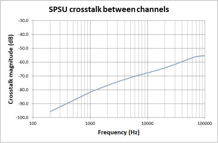
Cross-talk signal induced in channel 2 resulting from an excitation drive current in channel 1 plotted as a function of frequency:

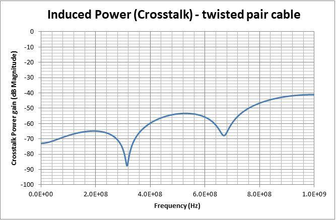
Cross-talk signal induced in one conductor of a twisted pair resulting from an excitation drive current in a conductor of another twisted pair in the same cable construction, plotted as a function of frequency.  Each pair is shielded with shields grounded to instrument ground:


The crosstalk measurements shown were measured on a 180cm length of cable. Cross-talk increases with frequency as expected.

The crosstalk measurements shown were measured on a 180 cm length of cable. Cross-talk increases with frequency as expected.

ItemValueValueValueValue
Cut-off Frequency170Hz1.85kHz12kHz110kHz
Pass band85Hz900Hz5KHz40kHz
Insertion loss over passband<0.6dB<0.6dB<1.0dB<1.0dB
Frequency rejection-45dB @ 100kHz-33dB @ 100kHz-36dB @ 1MHz-24dB @ 1MHz

A Bode plot of filter frequency response shows the different cut-off frequency configurations:

Related Applications

Nanomaterial Growth and Characterisation