Oxford Instruments NanoScience Contributes Cutting-Edge Technology to OQC’s…
Applications
.png)
Provides experimenters with an end-to-end method of protecting sensitive samples from accidental electrostatic discharge (ESD).
Can be used with Proteox, Teslatron and experimental measurement probes
High quality measurement grade cables
Low noise
The SampleProtect Switching Unit (SPSU) is a 24-channel unit in a 3U high enclosure designed for 19” rack mounting. The 24 signal lines are configured in 12 twisted pairs. At the rear of the unit there are 2 x 50-way sub-D connectors. One connector is used to connect all the signal lines to the measurement probe (or cryostat), the second is a feed-through link to connect any of the lines to additional instrumentation as an alternative to the individual BNC and Twinax connectors on the front panel. The 50-way connectors accept the SPSU Measurement Cable (quoted separately). With this connection configuration, the unit switches can be used to switch any of the signal lines between signal, open, measurement ground or protective ground.

The measurement cable is a carefully specified cable constructed of 13 twisted pairs, 10 pairs of 26 (19/38) AWG tinned Cu and 3 pairs of 22 (19/34) AWG tinned Cu. Each pair is individually screened with a foil screen. Each screen has external insulation to isolate it from all the other screens. Each screen also has a drain wire.
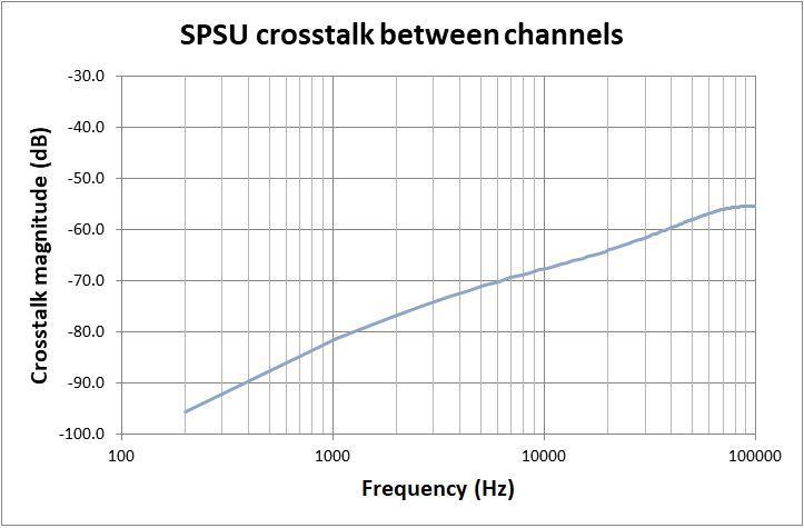
In addition, the cable has an overall foil screen which has internal insulation plus an external screen braid. The overall screen also has a drain wire. This construction facilitates overall screening with the outer screen connected to protective ground but in addition any pair can be screened to a specific measurement ground for that channel. The cross-talk increases with frequency as expected and is shown in specifications.
| Item | Value |
| Temperature Range | 0 to 40° C |
| Voltage rating | 50 VRMS |
| Recommended Frequency Range | DC – 100 kHz |
| Mutual Capacitance | 38 pF @1 kHz |
| Line Inductance | < 0.30 µH |
| Conductor DC line Resistance | < 0.18 Ω @20° C |
| Shield DC line Resistance | < 0.12 Ω @20° C |
Cross-talk signal induced in channel 2 resulting from an excitation drive current in channel 1 plotted as a function of frequency:

| Item | Value | Value |
| 26AWG pairs | 26AWG pairs | 22AWG pairs |
| Number of twists | 12 /ft (minimum) | 12 /ft (minimum) |
| Temperature Range | -40 to 80°C | -40 to 80°C |
| Voltage rating | 300VRMS | 300VRMS |
| Mutual Capacitance | 30pF/ft @ 1kHz | 38pF/ft @ 1kHz |
| Ground Capacitance | 54pF/ft @ 1kHz | 68pF/ft @ 1kHz |
| Characteristic Impedance | 55Ω | 43Ω |
| Line Inductance | 0.18µH/ft | 0.16µH/ft |
| Conductor DC line Resistance | 38Ω / 1000ft @ 20°C | 15.5Ω / 1000ft @ 20°C |
| Shield DC line Resistance | 34Ω / 1000ft @ 20°C | 14.5Ω / 1000ft @ 20°C |
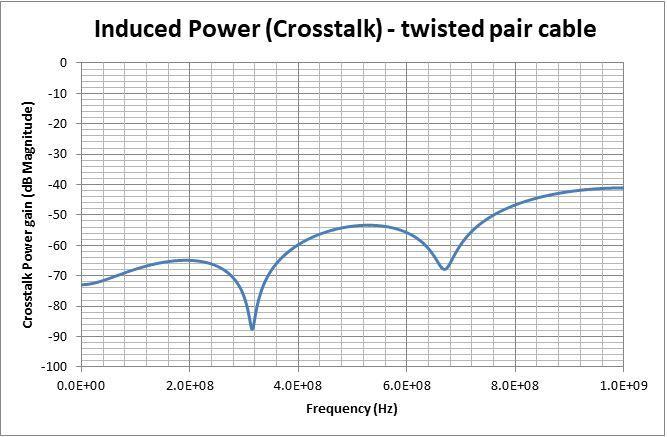
Cross-talk signal induced in one conductor of a twisted pair resulting from an excitation drive current in a conductor of another twisted pair in the same cable construction, plotted as a function of frequency. Each pair is shielded with shields grounded to instrument ground:
The crosstalk measurements shown were measured on a 180cm length of cable. Cross-talk increases with frequency as expected.
